ISO Boom Specification
ISO Boom Specification 2006
- The ISO boom may utilise either aluminium or carbon sections.
- In either case, the boom will utilise the Superspars end fittings (Superspars Boom Inboard End Round Section and Superspars Boom Outboard End Round Section).
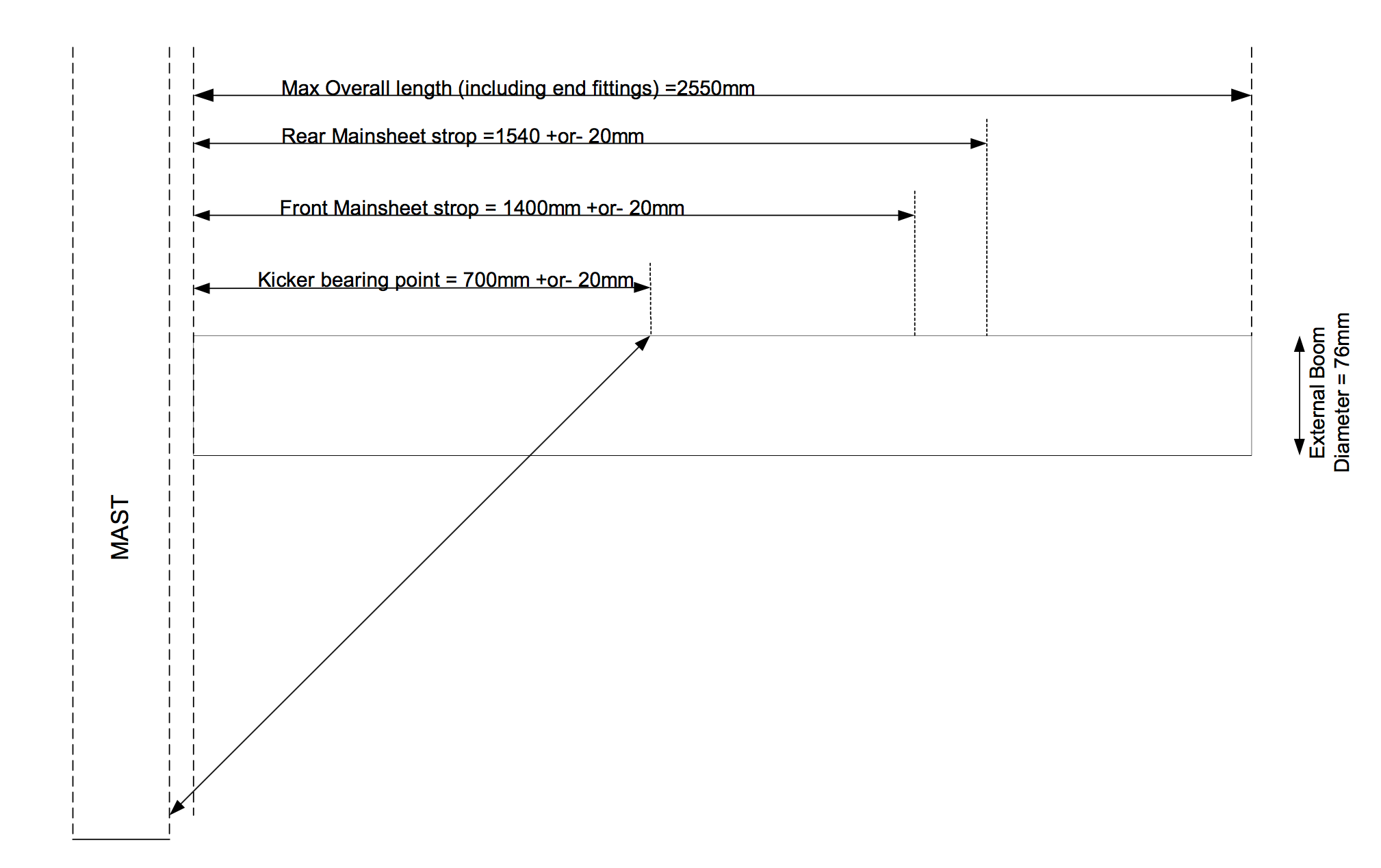
- The external dimensions are as shown in the diagram below.
- The measurement dimensions of the kicker and mainsheet strops are as shown in the diagram below.
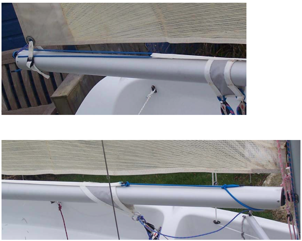
- If rivets are used for kicker and mainsheet strops, it is recommended they should be on the top of the boom where the boom is in compression.
- Alternatively the kicker and mainsheet may be located by use of over-boom strops without the need for holes being drilled in the main load bearing area of the tube.
- The kicker and mainsheet strops can be made from rope or webbing loops and should be positioned as detailed below.
- The slider in the outer end of the boom may be replaced by a Velcro strap or spectra loop.
- The 2:1 outhaul purchase will remain the same as original ISO booms and is contained inside the boom with the jamming cleat on the underside of the inner end of the boom nearest the gooseneck.
Boom diagram
Strop arrangement to avoid drilling holes in the boom